NASA Contractor Report 4707
Contract NAS8-38856
Prepared for Marshall Space Flight Center
by A.J. Piekutowski
University of Dayton Research Institute
300 College Park
Dayton, Ohio 45469
Formation and Description of Debris Clouds Produced by Hypervelocity Impact
ABSTRACT
NASA Contractor Report 4707 on the formation and description of debris clouds produced by hypervelocity impact by A.J. Piekutowski of the University of Dayton Research Institute using a 50/20 mm, two-stage, light-gas gun and Scandiflash Flash X-ray system XT150 Flash X-ray tubes. Forty-three tests were performed to examine the formation of debris clouds produced by the hypervelocity impact of aluminum spheres with thin aluminum sheets. All tests provided multiple-exposure, orthogonal-pair Flash radiographs of the debris clouds produced by the impacts. Measurements taken from the Flash radiographs were used to determine: (1) the velocity of a number of characteristic points in the debris clouds; (2) fragment sizes; and (3) fragment-size distributions.
ACKNOWLEDGEMENTS
A portion of the analytical effort and six of the tests described in this report were performed under Prime Contract NAS8-38856 on Subcontract A71447 with Martin Marietta Manned Space Systems (MMMSS). The author wishes to gratefully acknowledge Dr. Joel Williamsen, NASA Marshall Space Flight Center and Dr. Norman Elfer (MMMSS) for their support of this work. He also wishes to express his appreciation to Mr. Burton Cour-Palais of McDonnell Douglas Space Systems Company, Dr. Robert Schmidt of Boeing Defense & Space Group, and Dr. Lalit Chhabildas of Sandia National Laboratories for the use of radiographs and data from tests performed for them at the University of Dayton Research Institute. Special thanks are due to Dr. Schmidt for providing several of the thinner 6061-T6 bumper-sheet materials used in the tests and to Dr. Marvin Alme of Alme and Associates for his efforts in providing the plots used in Figures 32 and 58. Finally, the contributions of data and/or figures by the following are gratefully acknowledged: Drs. Dennis Grady, Marlin Kipp, and Timothy Trucano of Sandia National Laboratories and Drs. Charles Anderson, Jr. and Scott Mullin of Southwest Research Institute.
The author would also like to express his appreciation to the following associates at UDRI: The Office of the Director, for support provided for the range and equipment tests; Kevin Poormon, for his careful assistance in performance of the tests and discussions of test results; Dr. Alan Berens, for performing the statistical analyses of the fragment-size frequency distributions; Donald Jurick, for many helpful discussions; Robert Gooding and Chuck Blair, for performing the test firings; Tim Klopfenstein, for his care and spirit of cooperation in fabricating the sabots, targets, target fixtures, and all expendable materials used in firing the two-stage, light-gas gun; Richard Tocci and John Moreau, for their careful handling and printing of the radiographs; and Dale Grant, for performing the electronic image analysis of spall-shell fragments and for preparing the micrographs of the bumper-sheet sections.
The following excerpts are from the report:
Section I. Introduction
Since astronomers first envisioned sending craft and travelers into space, they have expressed concern for the protection of spacecraft from the accidental impact of meteoroids. They realized that spacecraft with walls thick enough to absorb the impact of a meteoroid would be impractical and considered alternate forms of wall construction. In 1947, F.L. Whipple described the operation of a double-wall system that could be used to provide the required protection. A thin, sacrificial outer sheet, known as a bumper or shield, would completely disintegrate the meteoroid upon impact, forming a debris cloud composed of meteoroid and bumper fragments. The debris cloud would disperse as it moved across a short standoff space toward the inner or pressure wall of the spacecraft. The inner wall would be somewhat thicker than the bumper and resist the impact of the cloud of meteoroid and bumper debris, thus protecting the contents of the spacecraft. Use of this simple shield-and-wall construction (or Whipple-bumper system) permitted a significant reduction in the weight of the spacecraft.
As interest in space travel by manned and unmanned vehicles became a national priority, numerous investigations of a wide variety of hypervelocity impact phenomena were undertaken. See, for example, the proceedings of the seven Hypervelocity Impact Symposia held between 1955 and 1964 and the AIAA Hypervelocity Conference held in 1969. A number of the studies described in these proceedings and other contemporary references were executed to evaluate performance of spacecraft shield systems. Although many materials and projectile shapes were used to simulate micrometeoroids, aluminum spheres were used as simulants in a significant fraction of the shield studies. Determination of the ballistic limit of a shield, optimization of a shield against a specific threat, and/or development of design criteria were the usual purposes for most test programs. Occasionally, radiographs or high-speed photographs of “typical” debris clouds produced during the tests were presented with test results. Only rarely were quantitative descriptions of the debris clouds given and when descriptions were provided, they were not systematic (i.e., did not describe changes in the debris-cloud morphology as a result of changes in impact velocity, bumper thickness, etc.).
Aluminum spheres continue to be used in shield studies as simulants of orbitaldebris fragments [15-18]. This report critically examines the aluminum sphere/thin aluminum sheet (projectile/bumper) interaction occurring during hypervelocity impact and the debris clouds produced as a result of this interaction. Although the impact velocities of the tests described in this report are well below the closing velocities of debris fragments with spacecraft, they do represent the state of the art in current test capabilities. Detailed understanding of the impact process at these reduced velocities is essential when extending the results of the reduced-velocity tests to estimate the response of spacecraft walls to impacts occurring at velocities high enough to completely melt and vaporize the fragment and the impacted area of the shield. It is the author’s hope that the data presented in this report will be used to validate the adequacy of computational techniques that must be used to evaluate shield performance for the range of impact conditions that are beyond current test capabilities. Every effort was made to provide detailed and high-quality, quantitative data, and to make the presentation of test results, analysis, and discussion of test results as relevant to the formation of debris clouds as possible. The effect (pass/fail) of the impact of the debris cloud on a rear wall was a secondary consideration. However, descriptions of the damage patterns produced on the witness plates used for the tests are provided.
A portion of the analysis presented in this report was done with support provided by NASA Marshall Space Flight Center (NAS 8-38856) on Subcontract A71447 with Martin Marietta Manned Space Systems. Results of a set of 43 tests are presented in detail. This set of 43 tests consisted of: (1) six tests performed specifically to examine debris-cloud formation as part of the funded analytical effort; (2) two tests performed for McDonnell Douglas; and (3) 3 5 tests supported by the Office of the Director of the University of Dayton Research Institute (UDRI). Where appropriate, limited results of other tests performed at UDRI are also presented. The data obtained from the 35 UDRI tests were incidental to the main objective of the gun firings – evaluation of gun loading conditions, dynamic testing of instrumentation, determination of exact loading conditions for tests where impact velocity was critical, etc. Use of a bumper sheet, witness plate, and Flash X-rays was all that was required to obtain the data presented in this report.
In the tests, two aluminum alloys were used for the projectiles and three aluminum alloys were used for the thin bumper sheets. A detailed listing of the projectile diameter and material, and bumper-sheet thickness and alloy is given in Section II for each test. Sufficient test data were available to permit an evaluation of the effect of bumper-thickness-to-projectile-diameter ratio (t/D), impact velocity, scale, and material on the debris-cloud formation process. The evaluation focused on tests using thinner bumper sheets but was limited in terms of the range of data for each set of test parameters and the number of tests (usually one) at each set of test conditions. The analyses and discussions represent an interpretation of the formation of debris clouds that was based on the data available at the time the report was prepared. Sufficient data were available to permit determination of trends and reasonable speculation on behavior in those regions where data were not available.
Several types of data were obtained. Measurements taken from multipleexposure, orthogonal-pair Flash radiographs permitted determination of the velocity of a number of characteristic “points” in the debris cloud, fragment sizes, fragment-size distributions, and sufficient data to allow a user of this report to reconstruct the debris cloud in terms of shape and position as a function of time after impact. Measurements were also made of the hole in the bumper sheet and of the damage pattern produced on witness plates placed downrange of the bumper. A complete listing of data available for each test is tabulated at the end of Section II.
Radiographs and a description of selected debris clouds produced by the normal impact of a sphere with a single-sheet bumper are presented in Section III. In Section IV, results of an analysis of the projectile fragments in the debris cloud are presented and discussed for a number of tests. Results of bumper-hole diameter measurements and micrographs of sections of representative bumper sheets are presented in Section V.
A model for the projectile-bumper interaction which occurred during hypervelocity impact is presented in Section VI. The model described the processes leading to the formation of the various debris-cloud elements. Distribution of mass in the debris cloud and within the debris-cloud elements is discussed. A method for estimating the state of material in the debris cloud is developed and used to estimate the properties of debris clouds formed by impacts at velocities high enough to produce aluminum vapor. The estimated debris-cloud properties are qualitatively compared with debris clouds produced by the impacts of cadmium spheres with cadmium sheets. Impact velocities for the cadmium tests ranged from velocities which produced only solid fragments to velocities which produced considerable vaporization of the cadmium sphere and bumper. Finally, a description of shock propagation in the bumper is given. The model presented in Section VI is based on observations, measurements, and analysis of data presented in Sections III, IV, and V. For some readers, Sections III, IV, and V will serve only as sources for data and may not be relevant to their interests. A quantitative description and discussion of the damage patterns produced on the witness plates used for the tests is presented in Section VII. In Sections VIII, IX, and X, the limited results of tests with multicomponent shields, oblique impacts, and nonspherical projectiles, respectively, are presented.
Section II. Experimental Materials and Procedures
All tests described in this report were performed in the UDRI Impact Physics Laboratory using the 50/20 mm, two-stage, light-gas gun shown in Figure 1. Impact velocity determinations were made with use of four laser-photodetector stations installed at various locations along the flight path of the projectile. Passage of the projectile through a laser beam directed into each photodetector produced a momentary drop in the output signal of the photodetector. Measurement of the time between the electrical pulses formed as the projectile moved downrange permitted the computation of the projectile velocity between any pair of laser-photodetector stations. Accuracy of the impact velocity determination was better than 0.5 percent. A detailed listing of the materials used in the tests and a description of the experimental procedures is given in the remainder of this section.
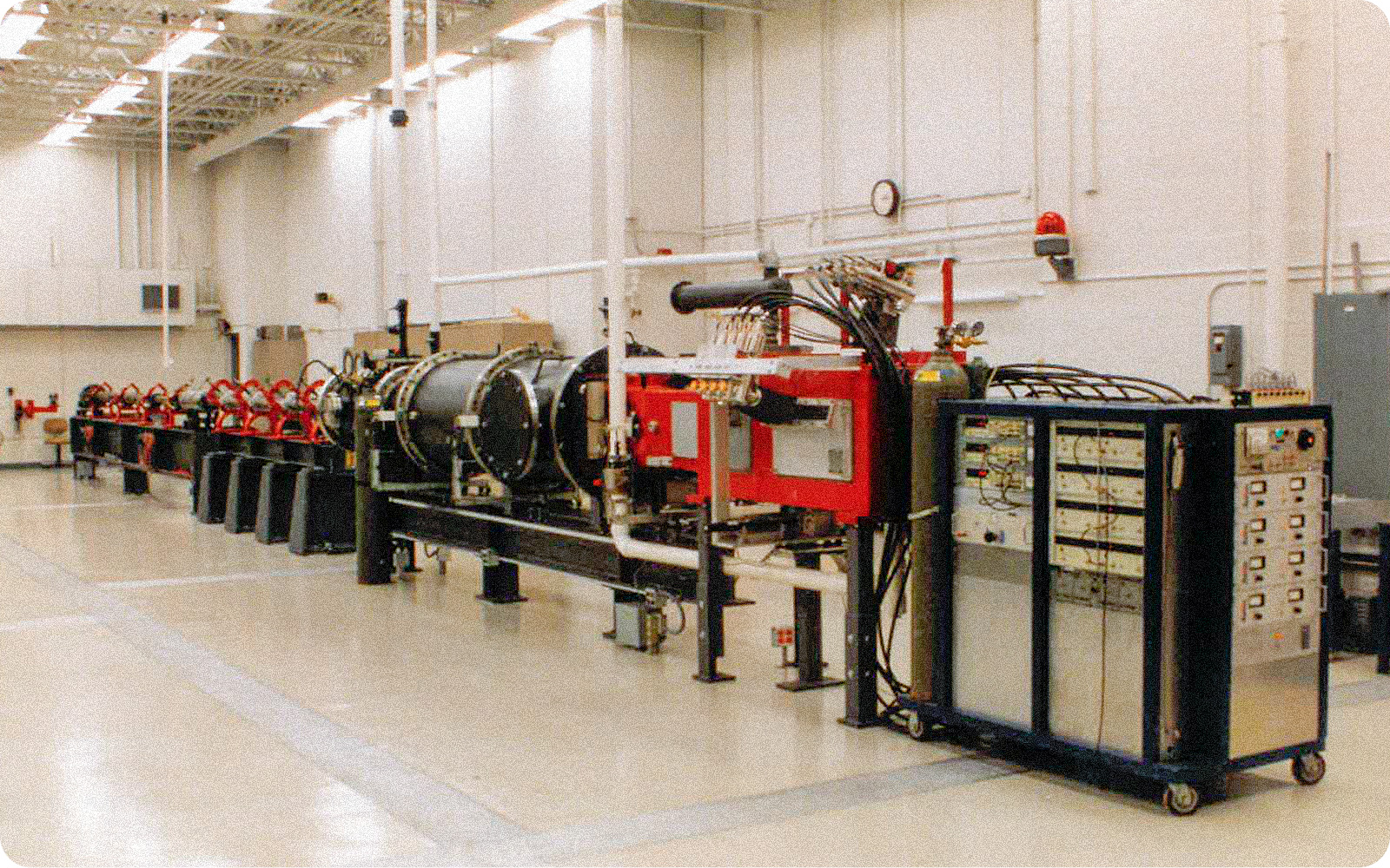
Figure 1. View of University of Dayton Research Institute 50/20 mm, two-stage, light-gas gun.
View is from instrumentation/target chamber end of range.
A. Materials
Three diameters of 2017-T4 aluminum spheres (6.35 mm, 9.53 mm, and 12.70 mm) were used as projectiles for the tests. A test employing a 12.70-mm-diameter, 1100-0 aluminum sphere was also performed. Various thicknesses of 1100-0, 2024-T3, and 6061-T6 aluminum sheets, ranging from 0.25 mm to 4.80 mm, were used as bumpers. Bumper-sheet thickness, shot number, and projectile weight ( centered under thickness and shot number) are shown for each projectile diameter and alloy in Table 1. The shot number given in Table 1 uniquely identifies each test. Shot number and/or t/D ratio will be used as the index for the sorting of tabulated data presented in this report.
A witness plate was placed approximately 38 cm downrange of the bumper for each test. The large spacing between the bumper and the witness plate permitted several Flash radiographs of the debris cloud to be made as the cloud traversed the space between the plates. In addition, it allowed the debris to disperse sufficiently to isolate individual fragments in the X-ray view taken just before the cloud struck the witness plate.
Four thicknesses of 6061-T651 aluminum plate and one thickness of 2219-TS l, 2219-T87, and 5456-H116 aluminum sheet were used as witness plates. The witness plates were merely used to record the damage pattern produced by the impact of the debris cloud; the posttest condition of the plate was not relevant to the test objectives. However, when selecting a witness plate, every attempt was made to use a plate that was thick enough to withstand the impact (avoiding a large blowout-type failure) and capable of providing a good record of the damage pattern. Two-inch-thick hardwood planks were used as witness plates for four tests. Wood was used for these tests to minimize damage to the X-ray film which occurred when heated ejecta fragments (from the witness plate) come to rest on the X-ray-film cassettes. Foam blocks and rags were used, without witness plates, for five tests in which the projectiles were recovered.
B. Procedures
I. Test Setup. All but two of the tests were performed with the bumper normal to the range center line. The thinner bumpers were 10.8 cm square and were securely taped to a 3.18-mm-thick, 15.2-cm-square aluminum frame that had an 8.9-cm-square opening cut in its center. The thicker (I mm or greater) bumpers were 15.2 cm square and were held at their corners by screws passing through the sheets into appropriate support posts. The bumper sheets used for the oblique tests were taped to the same frame used to hold the bumpers for the normal-impact tests. However, the frame was attached to a fixture that could be rotated to obtain the desired oblique impact angle. The witness plates for all tests were supported by a framework that extended from the rear wall of the target chamber.
Figure 2. View of target chamber showing multiple orthogonal pairs of Flash X-ray heads,
chamber windows, and shielding.
2. Multiple-Exposure, Orthogonal-Pair Flash Radiography. Four pairs of fine-source, soft, Flash X-rays were used to observe the projectile and debris cloud. The X-ray heads were accurately positioned on the target chamber to provide simultaneous, orthogonal views of the debris clouds. A typical test setup is shown in Figure 2. Field Emission Model 2772, 180kV dual pulsers and Scandiflash 150kV remote tubeheads (Model XT150) with soft X-ray adapters and 1 mm diameter sources were used to produce the radiographs. The X-ray tubeheads were positioned so that the source-to-object (range center line) distance was 64 cm. Kodak Direct Exposure Diagnostic Film (Cat 154 2463) was placed in a paper film cassette. The side and top film cassettes were positioned about 9.6cm from the range center line using a film-holding fixture attached to the target-chamber floor.
Details of the shielding used to produce the multiple-exposure radiographs are illustrated in Figure 3. The first pair of X-ray heads was used to view and record the position of the projectile a few microseconds before impact. This view verified projectile integrity and permitted an accurate determination of the time after impact for the various views taken of the debris cloud after its formation. Normally, the first two debris-cloud views were taken when the leading edge of the cloud was about 4 cm and 12 cm downrange of the bumper. The two pairs of X-ray heads used to produce these views were positioned directly above and 7.87 cm downrange of the bumper. The fourth pair of X-ray heads was fired when the debris cloud was about 30 cm downrange of the bumper. The delay in firing this pair of heads allowed the cloud to expand and permitted a more detailed examination of the cloud structure. The fourth pair of X-ray heads was positioned 15.8 or 31.5 cm downrange of the bumper to provide oblique (approximately 13 degrees from normal) or normal views of the cloud, respectively.
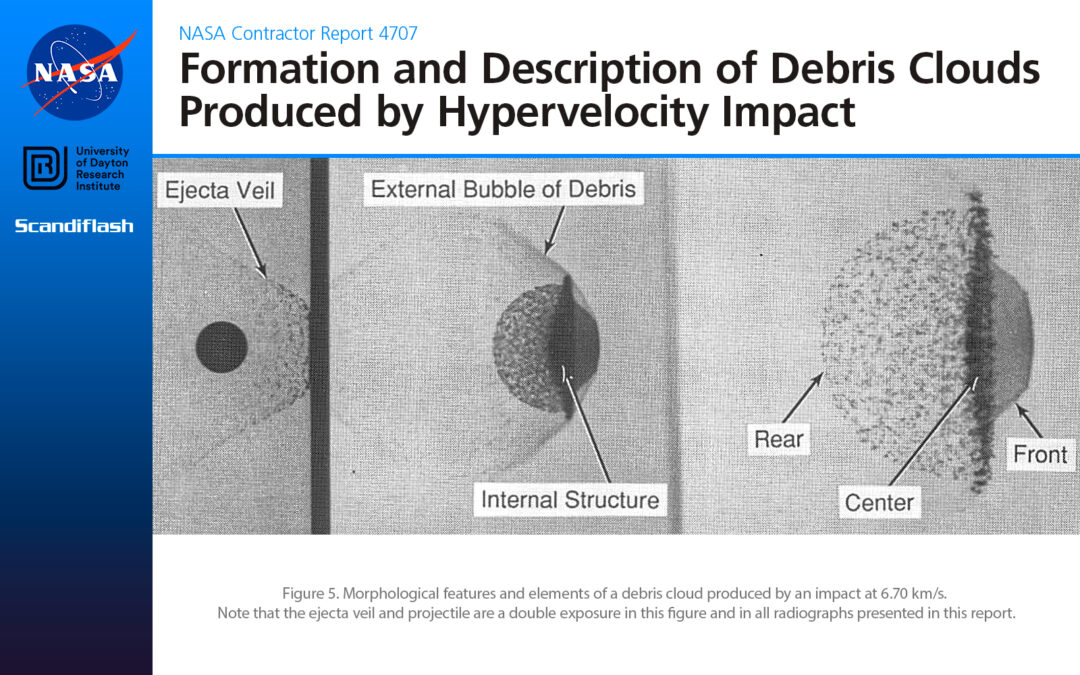
A pair of prints of multiple-exposure, Flash radiographs, obtained using the setup shown in Figures 2 and 3, are presented in Figure 4. Three features of this pair of radiographs require further explanation. First, the pre-impact view of the sphere and the ejecta veil generated by the impact were double-exposed in the first panel of the films. When prints of the radiographs were prepared for presentation in this report, the exposure of the film was carefully controlled during printing to bring out detail in the ejecta veil and to provide a background of about the same contrast level as for the single-exposed views. Second, the fourth pair of X-ray heads was positioned so that the side head (prefix “S” in shot number) was 31.5 cm downrange of the bumper and produced a normal view of the debris cloud. The top head (prefix “T”) was positioned 15.8 cm downrange of the bumper to produce an oblique view of the cloud. In other tests, these heads were placed to obtain two oblique views or two normal views. Finally, the largest available size of direct-exposure film was 8 x 10 inches. In order to “cover” the space between the bumper and the witness plate (as well as provide the pre-impact view), two pieces of film (one 4 x 10 inches and one 4 x 8 inches) were placed in an acetate film holder and the assembly was inserted in a standard 4-1/2 x 17 inch paper film cassette. A short piece of fine copper wire was placed along the upper and lower edges of the acetate film holder in the region where the pieces of film overlapped. When the film was exposed, the shadows of the wires left on each piece of film precisely indicated the relative position of the two pieces of film, thus facilitating joining of the prints of each for data analysis purposes.
3. Data Reduction. Data were obtained from three sources – the radiographs, the hole left in the bumper, and the damage pattern on the witness plate. The radiographs were used to determine the axial and radial velocities of a number of characteristic elements of the debris clouds. The position of each point in each of the debris-cloud views was measured and adjusted for film magnification. The adjusted or true distances were divided by the time between X-ray exposures to obtain the velocity of the point. The fourth or latetime view was also used to determine the dimensions of the large central fragment in the debris cloud and for the fragment-size and size-distribution analyses. Specific details of the measurements are presented as the data are introduced in Sections III and IV.
The diameter of the hole left in the bumper sheet was carefully measured using an optical comparator. Measurements were taken parallel and perpendicular to the rolling direction of the sheet stock. Eight of the bumpers had a section of the bumper and the lip region removed, mounted, and the cross section microscopically examined. Results of the hole-diameter measurements and a discussion of the findings of the microscopic examination are given in Section V.
Identifiable structures in the damage patterns, which were produced on the front and rear of the witness plates, were measured using a scale. The results and interpretation of these measurements are found in Section VII.
A tabulation of the various types of data available for each test is given in Table 2. Shown in the table are the number of Flash X-ray views made for each test. As noted, only two post-impact views were made for some of the tests. In some instances, debris velocities were limited to one or two points in the cloud. In others, the velocities of up to twelve points ( or pairs of points) were determined. Dimensions of three types of fragments were obtained for many of the tests. Bumper-hole diameters were recorded for all but one of the tests. Witness plate damage pattern measurements were obtained for all but twelve of the tests. Finally, sponsorship of the individual tests is also noted in Table 2.
An index is provided at the end of the report to assist the reader in locating radiographs, photographs of bumper sheets and witness plates, etc., used in the various figures presented in the report. The index is accessed with use of the shot number.
Learn more about Flash X-ray imaging solutions:
Contact a Hadland Imaging representative to learn more about Flash X-ray imaging solutions, ultra high-speed cameras & everything you need to get the job done right.
![]()
Keywords: A.J. Piekutowski, University of Dayton Research Institute, Kevin Poormon, NASA, Scandiflash, Flash X-ray, XT 150, 150kV, radiography, radiographs, orthogonal pair, spacecraft shielding, Whipple-bumper system, light-gas gun