AUTHORIZED REPRESENTATIVE OF LAVISION

LaVision HighSpeed IRO X Image Intensifier
The ultra high-speed imaging solution for challenging illumination scenarios (chemiluminescence) and when recording high-speed phenomena at extremely short gating times – down to 10 nanoseconds.
Ultra High-Speed Intensified
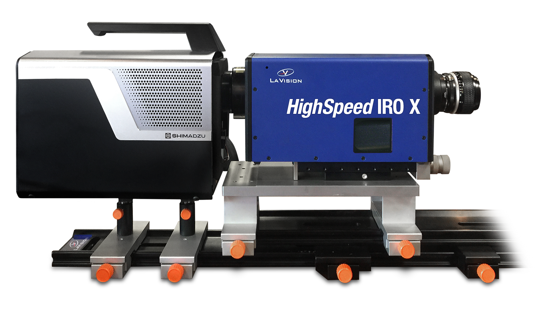
High-Speed Intensified Relay Optic System – perfectly pairs with the Shimadzu Hyper Vision HPV-X2 ultra high-speed video camera with up to 10 million frames per second with 6x higher sensitivity (ISO 16000) than conventional video cameras, intensified.
Key Features:
- 2-Stage image intensifier (MCP + Booster)
- S20 or S25 Photocathodes
- P46 Phosphor screens
- Spectral range of 190–800 nanometers
- Highest UV sensitivity
- Sensitivity peak within visible range
- Short gating times down to 10 ns
- Enhanced lens coupling with reduced vignetting
- Nikon F mount
- 500 mm Optical rail, clamps, posts & holders
Intensify Your High-Speed Imaging.
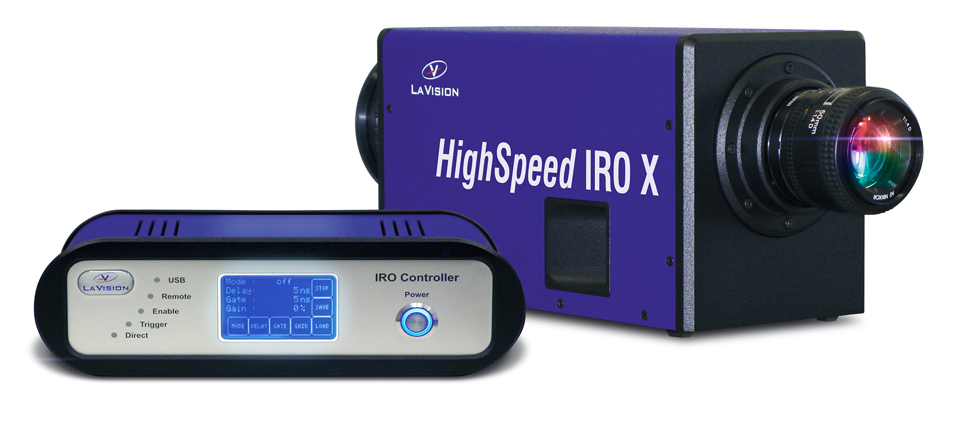
The LaVision HighSpeed IRO X is an intensified relay optic system equipped with an extremely fast gated, high-precision shutter control. It improves the performance of high-speed and ultra high-speed camera systems and is the perfect solution when recording light emission in chemiluminescence research and when extremely fast gating times are needed.
 The HS IRO X is a lens-coupled system that mounts to the front of high-speed and ultra high-speed cameras. It has an optimized image intensifier system with fast P46 phosphors for high frame rate (HFR) recording without ghosting into subsequent frames.
LaVision HighSpeed IRO X Image Intensifier is configured as a two-stage MCP (microchannel plate) with Booster system. The two-stage intensifier system configuration yields approximately 10 times higher signal output compared to a single-stage system. For highest frame rates a two-stage system is required to get adequate dynamic behavior. The maximum achievable frame rate also depends on the parameters of the high-speed or ultra high-speed camera.
The HS IRO X lens system is a 1:1 optics coupling optimized for highest collection efficiency, resolution and minimized shading (center to rim) for 25 mm diameter objects. The 1:1 coupling optimally matches large CMOS high-speed and ultra high-speed camera sensors – illuminating the entire sensor with the intensified image.
The IRO Controller ensures optimized synchronization to the camera offering various timing modes and automatic enabling/disabling synchronous to the camera recording. Controlling is done via local keypad or remote with the IRO App or with the LaVision DaVis app via USB interface. The controller offers three timing modes: Internal, Direct and Burst Sequence.
The LaVision HighSpeed IRO X system includes a mounting kit consisting of a 500 mm optical rail, three clamps, posts and holders. The optional HighSpeed IRO Focusing Base Mount allows easy focusing of the HS IRO X to the camera sensor.
Inside the LaVision HighSpeed IRO X Image Intensifier
exploded view of two-stage image intensifier
illustrations by Hadland Imaging are artistic renderings and not to scale
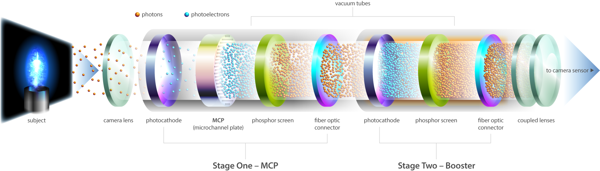
Stage One – MCP
Incident particles (photons) enter the intensifier (a vacuum tube) through a camera lens and pass though a photocathode charged with high voltage, which converts the photons to photoelectrons. Photoelectrons pass through millions of channels in the MCP (microchannel plate), accelerated by variable high voltage and amplifying with each collision on the channel walls. Photoelectrons are reverted to photons as they pass through a phosphor screen charged with high voltage. A fiber optic connector passes the amplified image signal to the booster (stage two) for additional intensification.
Stage Two – Booster
The booster consists of a second photocathode and phosphor screen, charged with high voltage to convert and amplify photoelectrons for increased resolution for high-speed & ultra high-speed imaging.
Fiber optic connectors efficiently transfer amplified light to the booster and to the coupled lenses, which are used to optimize exposure, match the size of the camera’s sensor and to maximize spatial resolution of the intensified image capture.

MCP Tech Specs
Material: glass
MCP Diameter: 25 mm
Channel Diameter: ~5 µm
Channel Pitch: ~6 µm
(distance between channel centers)
MCP Depth: ~400 µm
(channel length)
Number of Channels: ~20 million
The MCP (microchannel plate)
Microchannel plates (MCP) are specially fabricated glass plates containing millions of channels used to amplify electron signals, similar to a secondary electron multiplier (SEM). Unlike an SEM, the MCP contains millions of channels – each working as an independent electron multiplier – the MCP is an assembly of millions of miniature SEMs.
Microchannel Plates have a combination of unique properties like high gain, high spatial resolution and high temporal resolution. They can be used in a large variety of applications including imaging spectroscopy, electron spectroscopy and microscopy, mass spectrometry, astronomy, molecular and atomic collision studies, cluster physics, and others. Most of these applications require only some of the MCP’s properties, for example, Time-of-Flight Mass Spectrometry require high temporal resolution of MCPs and imaging of single atoms in field ion microscopes or X-ray imaging of the Sun require mainly spatial resolution. Particle analyzers may be produced by using an MCP detector at the output of a electrostatic and/or magnetic dispersion system. Very high sensitivity optical UV and EUV and X-ray spectrometers can also be produced with appropriate filtering and dispersive elements. The same microchannel plate technology is used to make visible light image intensifiers for night vision goggles and binoculars.
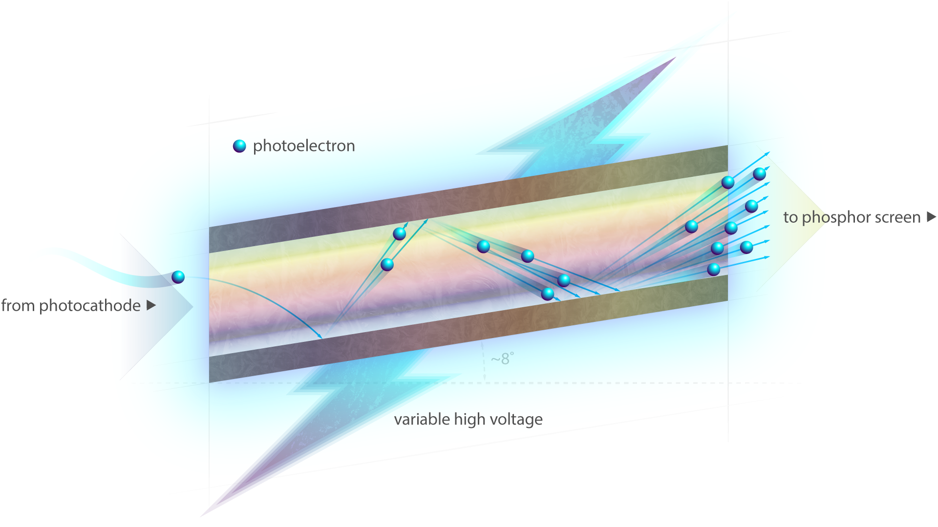
Inside the MCP
The MCP consists of a periodic array of millions of extremely small diameter glass capillaries (channels) fused together and sliced into a thin plate. A single incident particle (photoelectron) enters a channel and emits an electron from the channel wall. Secondary electrons are accelerated by an electric field developed by variable high voltage applied across both ends of the MCP. Photoelectrons travel along their parabolic trajectories until they strike the channel surface and produce additional secondary electrons. This process is repeated multiple times along the channels, yielding a cloud of several thousand electrons, which emerge from the rear of the plate.
The individual channels of the MCP confine the pulse and the spatial pattern at the rear of the MCP preserves and intensifies the image pattern on the front surface of the MCP.
The output signals of the MCP pass through a phosphor screen for photon conversion and then through a fiber optic connector for additional intensification in the booster.
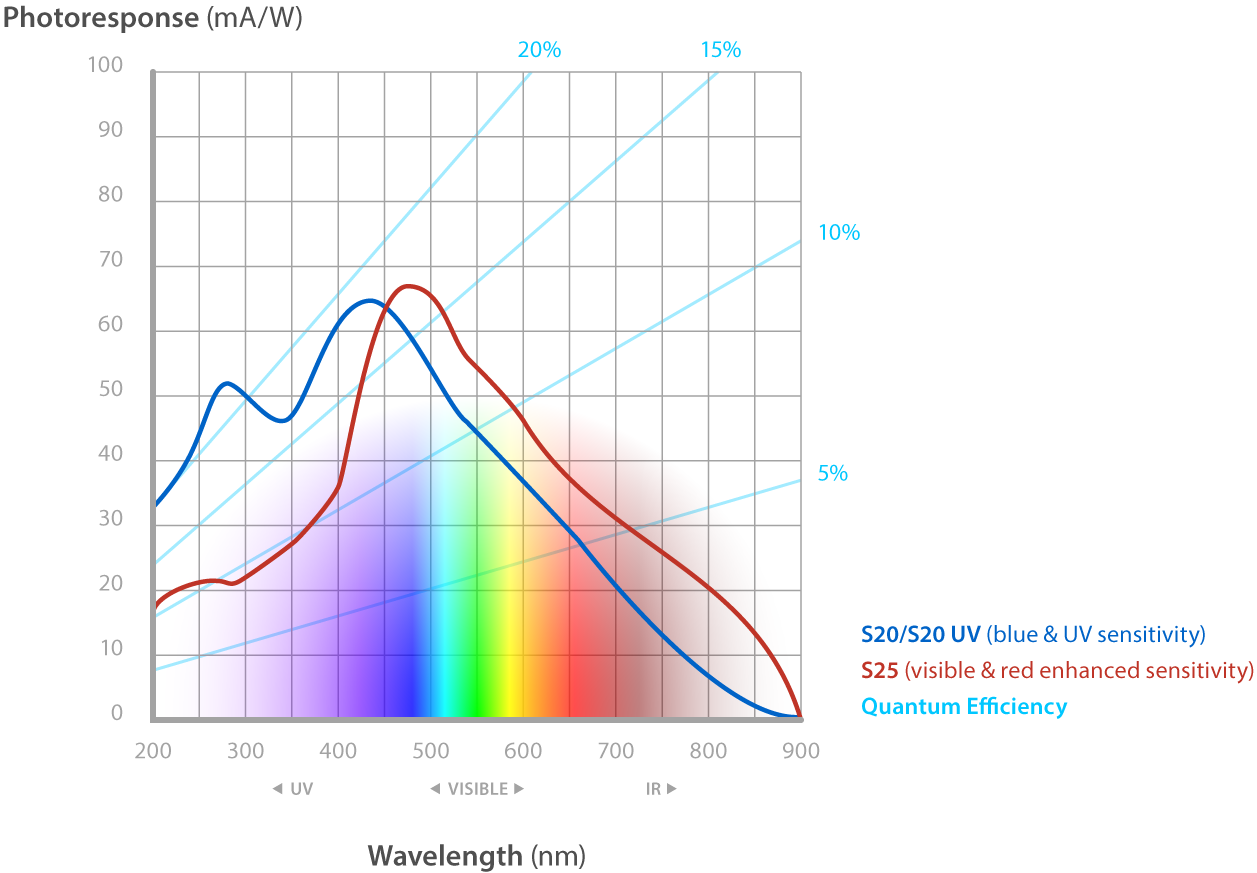
Photocathode Sensitvity
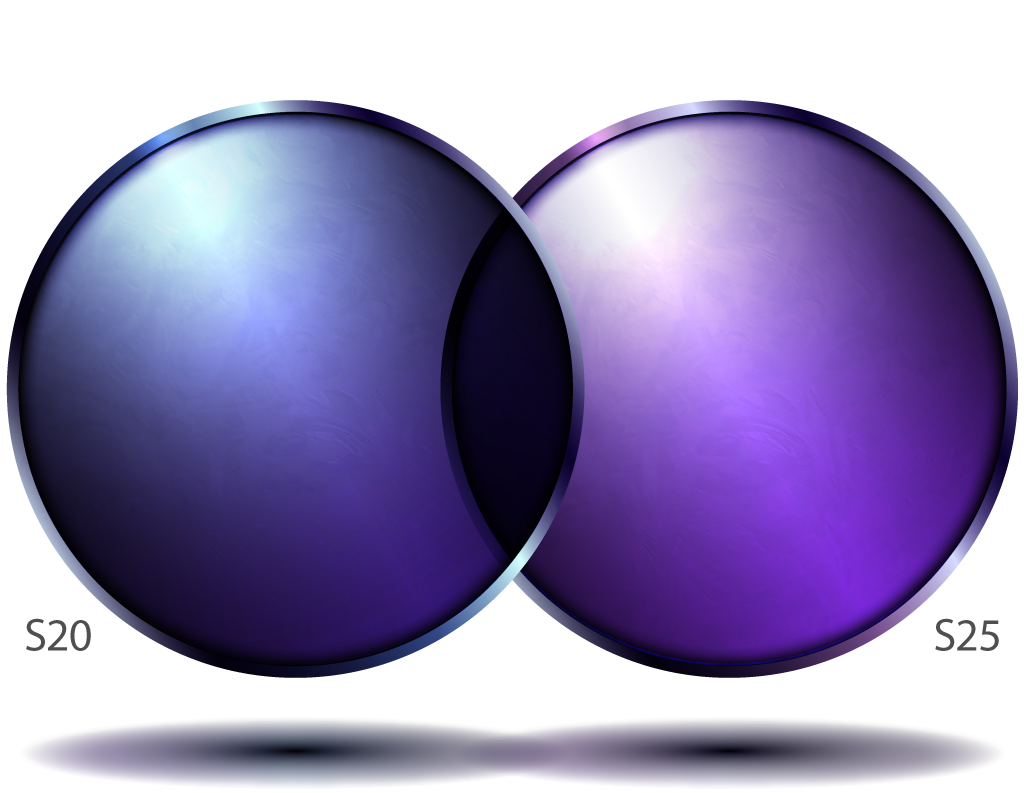
Tech Specs
S20: blue & UV sensitivity
S25: visible & red enhanced sensitivity
Diameter: 25 mm
Linearity at Full Signal Level
The dynamic behavior of photocathode sensitivity is determined by the maximum amount of recharge current and optimized component configuration. Depletion is an effect when the selected gain factor cannot be maintained in a stable operation and when the recharge current cannot deliver the required number of electrons for that gain. At smaller signal levels (fewer counts) this will show up at higher repetition rates.
The LaVision HighSpeed IRO X Image Intensifier maintains linearity at full signal level (1,024 counts for 10-bit cameras) up to extremely high repetition rates. The maximum signal current depends on pixel size and sensitivity of the camera sensor.
At a Glance
2 Stage image intensifier (MCP + Booster)
HighSpeed IRO X – 14.5 x 5.125 x 6 inches
IRO Controller – 7.875 x 10.25 x 3.25 inches
Enhanced lens coupling with reduced vignetting
Nikon F mount
500 mm optical rail, clamps, posts & holders
S20 or S25 photocathodes
P46 Phosphor screens
25 mm diameter
Spectral range of 190–800 nanometers
Highest UV sensitivity
Sensitivity peak within visible range
Short gating times down to 10 ns
Tech Specs
Specifications current as of March 2021 and are subject to change.
Illustrations of lens, photocathodes & phosphor screen are artistic renderings by Hadland Imaging and not to scale.
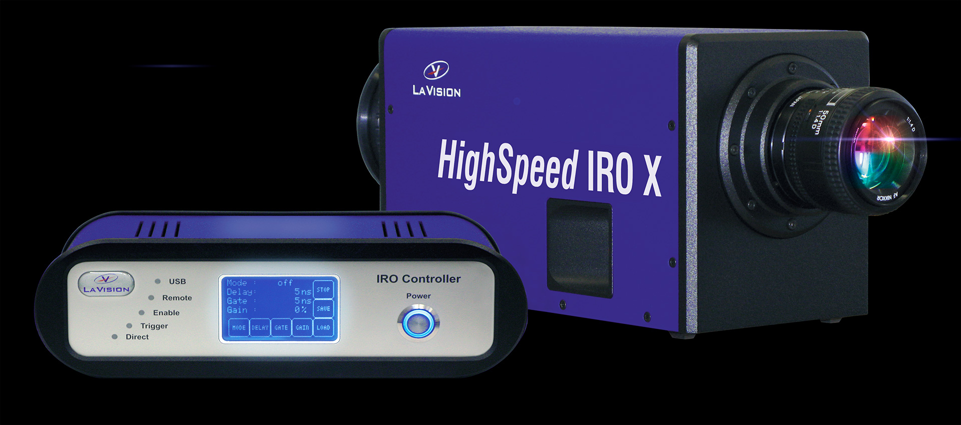
LaVision HighSpeed IRO X Image Intensifier & IRO Controller
An optional focusing mount with micrometer screw is available for precise alignment of the HighSpeed IRO X to the camera’s focal plane.
Dimensions
HighSpeed IRO X
IRO Controller
Focusing Base Mount
Size (LWH)
14.5 x 5.125 x 6 inches
(370 x 130 x 152 mm)
7.875 x 10.25 x 3.25 inches
(200 x 260 x 82 mm)
13.75 x 6.25 x 11.5 inches
(350 x 160 x 290 mm)
Weight
14.8 lb (6.7 kg)
4.4 lb (2 kg)
10.14 lb (4.6 kg)
Optical Axis Height
3.66 inches (93 mm)
Image Intensifier
Two-Stage System
Stage 1
MCP
Gen 2 proximity focused MCP
Stage 2
Booster
Gen 1 proximity tube
Diameter
25 mm
Input Window

Quartz
other available on request
Photocathode

S20
blue & UV sensitivity
Minimum gate 10 ns

S25
visible & red enhanced sensitivity
Minimum gate 10 ns
Phosphor Screen

P46
Decay Time <3 µs (to 1%)
General System Specifications
Spectral Range

190–800 nanometers
range varies with S20 or S25 photocathodes
Maximum Repetition Rate
Up to
300kHz / 10 ns Gate
Exposure Time
10 ns
Internal Mode
Lens Coupling
1:1 / η~12%
Input Lens Adapter
NIKON
F mount
Vignetting
<10%
Center to Rim
Electronics
Operation Modes
Internal Mode
Gating (exposure): 80 ms–10 ns (5 ns/3 ns with PS-delay option)
Delay: 0–80 ms
Delay/Gate Resolution: 5 ns steps (1ns with PS-delay option)
Direct
Gating (exposure): follows external TTL signal
Gate Minimum: 5 ns (3 ns optional)
Burst Sequence
Gating (exposure): 80 ms–10 ns (5 ns/3 ns with PS-delay option) with multiple gate pulses released by external trigger
Maximum Frequency: 2MHz corresponding to minimum cycle time = 3.3 µs for delay/gate entries
Programming
Remote control via USB interface or from control PC;
Local control via LCD keypad & display
Power Supply
110V or 230V
Non-Uniformity
+/–15%
MCP Intensifiers
+/–10%
Booster
(non MCP intensifiers)
Purchasing Options
Photocathode
S20
blue & UV sensitivity
S25
visible & red enhanced sensitivity
Warranty
one-year limited warranty
What are you waiting for?
Press the button already or call 1-888-43HADLAND (1-888-434-2352) to get your LaVision HighSpeed IRO X Image Intensifier (or at least find out more information).