
Scandiflash x QFXR:
Thickness Quantitative Flash X-Ray Imaging of Molten Metal Fragmentation
FXR reveals droplet breakup mechanisms to help prevent hazardous events.
Application note originaly published by Scandiflash, June 2026
Made in collaboration with Professor David L. Frost at the Department of Mechanical Engineering, McGill University, Montreal, QC, Canada.
ABSTRACT: Flash X-ray (FXR) imaging enables visualization of fast, opaque processes such as molten metal fragmentation in water. By applying proper calibration, FXR can be used not only for imaging but also for quantitative measurement of material thickness and mass distribution.
This application note describes the calibration procedure required to convert X-ray intensity into material thickness, using molten tin–water interaction experiments as an example. The approach demonstrates how accurate calibration and normalization transform radiographs into time-resolved quantitative data.
Thickness Calibration for Converting Radiographs into Mass Distribution
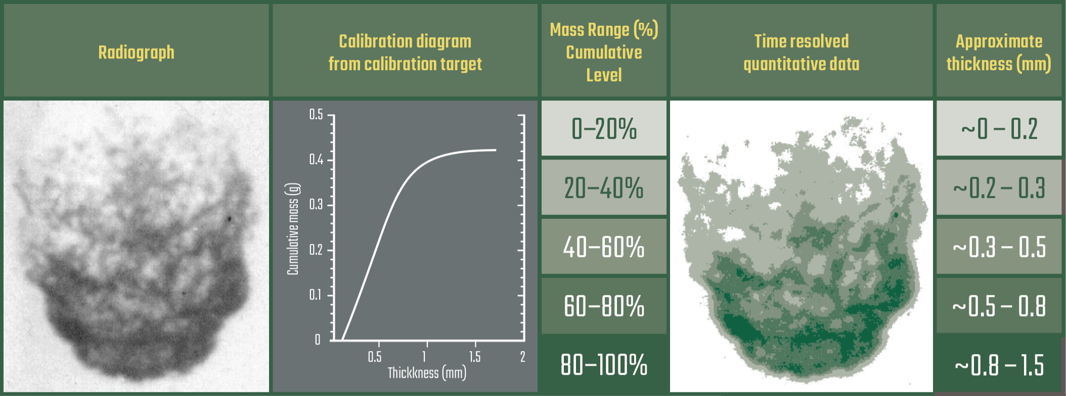
Table 1. Radiograph and time resolved quantitative data.
Equipment
- Scandiflash SCF150 Flash X-Ray System
- Kodak XAR-5 high-speed X-ray film
- Kodak Mini-R intensifying screen & cassette
- High-speed camera
Thickness Calibration Quick Checklist
- Choose correct FXR system and setup for appropriate thickness range.
- Fix setup (geometry, shielding, materials).
- Acquire calibration image (including whole image + step wedge).
- Extract intensity vs thickness.
- Fit calibration curve.
- Normalize images (background + flat-field).
- Apply to experiment.
- Respect limits.

Droplet sequence radiograph.
Droplet breakup is far more than a visual curiosity, it is a key multiphase flow phenomenon that governs how fluids mix, exchange heat, and form new interfaces. As droplets fragment, they create surface area that accelerates thermal and chemical interactions, influencing processes from industrial cooling to melt–coolant interactions where vapor explosions may occur.
Flash X-ray radiography enables the study of these systems by penetrating vapor bubbles and dense fragment clouds, revealing internal structures that cannot be observed optically. Beyond visualization, it allows quantitative analysis by converting image intensity into material thickness, and thereby estimating mass distribution within the evolving droplet.
Choice of System & Setup
The measurable thickness range is determined by the selected FXR system and operating voltage (kVp), which defines the energy spectrum and penetration capability. Selecting appropriate conditions ensures that the relevant fragment structures fall within the measurable range.
Measurement Setup
The full experimental configuration must be fixed prior to calibration, including geometry, shielding, and all materials in the beam path. In this work, the X-ray head was positioned 50 cm in front of the droplet and the detector 6 cm behind it, providing a balance between contrast and penetration.
Calibration Image Acquisition
A reference image is recorded using a calibration target with known thickness steps placed within the field of view. This image contains both the object and the thickness reference under identical conditions.
Intensity–Thickness Relation
Since Flash X-ray sources produce a broad spectrum, the measured intensity is given by:
I = ∫S(E)e–µ(E)x dE
Rather than solving this analytically, intensity values corresponding to known thickness steps are extracted from the calibration image.
Calibration Curve
These data are used to generate an empirical mapping between normalized image intensity and material thickness:
x = f(Inorm)
Normalization
All images are corrected using a combined normalization step:
Inorm = (Imeas – Ibg) ⁄ (I0 – Ibg)
This removes background signal and compensates for spatial variations in beam intensity.
Application to Experiment
The calibration function is applied pixel wise to radiographs of the fragmentation process, converting grayscale intensity into line of sight thickness and enabling spatial mapping of the droplet mass.
Using this approach, the thickness analysis reveals how mass is redistributed during fragmentation. Initially, material is stripped from the droplet surface, forming a fragment cloud. At low coolant velocities, vapor bubble collapse disperses fragments into a more uniform distribution, while at intermediate velocities mass remains concentrated near the droplet core. At high velocities, vapor formation is suppressed and fragmentation is dominated by hydrodynamic stripping, producing a more continuous downstream distribution. ■
![]()
About Scandiflash
Scandiflash, located in Uppsala, Sweden, has been pioneering Flash X-ray technology for over 50 years – helping scientists and researchers around the globe see through the toughest conditions. Scandiflash Flash X-Ray (FXR) Systems are valuable solutions to image through fire, smoke, metal and other materials during research using fast 20 nanosecond X-ray pulses for incredibly sharp ultra high-speed imaging. Scandiflash FXR Systems are available for indoor lab setups and for outdoor large-scale firing ranges, and can be tailored to meet the requirements for a variety of research applications.
Learn more about ultra high-speed Flash X-ray imaging solutions:
Contact a Hadland Imaging representative to learn more about Flash X-ray imaging solutions & everything you need to get the job done right.
Keywords: David L. Frost, Department of Mechanical Engineering, McGill University, QFXR, quantitative Flash X-ray imaging, Scandiflash